Pulse-width modulation can be used by a microcontroller to control the power supplied to other devices like LEDs or motors. It works by switching a digital pin on and off at a high frequency. The power supplied to the device is determined by the length of time the pin is on versus off. This relation is given as a percentage and is called the duty cycle.
Arduino API
The Arduino API allows you to use PWM and set the duty cycle with the function analogWrite(), which also works on the Attiny84:
byte PWM_PIN = 6;
byte dutyCycle = 127;
analogWrite(PWM_PIN, dutyCycle);
The variable dutyCycle can be set to a value between 0 and 255, whereby 0 means the pin is always off and 255 means it's always on. The problem is, that you cannot set the frequency of the output square wave. The default frequency seems to be either 250 Hz or 500 Hz, which is clearly not enough for certain use cases. To change the frequency, you have to set the appropriate flags in the Attinys registers manually. This post shows how to set these flags and how to create really high frequencies like 4 MHz.
Timer Configuration
On the Attiny84 and other Atmel chips only certain pins can be used for PWM output. Every PWM-pin is controlled by a certain timer and different chips have different timers. All this information can be obtained by reading the datasheet for the particular chip. The Attiny84 has two timers called Timer0 and Timer1 and four PWM pins. The pins 5 and 6 (Arduino digital pins 8 and 7 respectively) are controlled by Timer0 and the pins 7 and 8 (Arduino digital pins 6 and 5 respectively) are controlled by Timer1.
Timer0 is used by the Arduino environment for timing functions like delay(), millis() and micros() and many libraries depend on these. So by changing the frequency of Timer0 a lot of libraries will stop working correctly. For the sake of brevity I will describe only the configuration of Timer1 in this post. Timer0 works essentially the same, with some minor differences, which are outlined in the datasheet.
Register Description
Every timer has two registers to set its mode of operation. These registers are called "Timer/Counter Control Register" or TCCR for short. By setting and unsetting the bits in these registers, we can control the behavior of the timer. The following table shows all the bits for the registers TCCR1A and TCCR1B.
| Registers for Timer1 | |||||||||
|---|---|---|---|---|---|---|---|---|---|
| Bits | 7 | 6 | 5 | 4 | 3 | 2 | 1 | 0 | |
| TCCR1A | COM1A1 | COM1A0 | COM1B1 | COM1B0 | - | - | WGM11 | WGM10 | |
| TCCR1B | ICNC1 | ICES1 | - | WGM13 | WGM12 | CS12 | CS11 | CS10 | |
This looks very complicated, but it is actually quite easy if you read the datasheet.
Setting the Prescaler
With no prescaler enabled, the timer ticks at the full speed of the CPU clock frequency, which is usually too high for any practical purposes. The prescaler divides the CPU clock frequency into smaller chunks. With a prescaler of 256 the timer ticks once for every 256 CPU clock ticks. The prescaler is set with the bits CS12, CS11 and CS10.
| CS12 | CS11 | CS10 | Prescaler |
|---|---|---|---|
| 0 | 0 | 0 | Timer disabled |
| 0 | 0 | 1 | No prescaling |
| 0 | 1 | 0 | 8 |
| 0 | 1 | 1 | 64 |
| 1 | 0 | 0 | 256 |
| 1 | 0 | 1 | 1024 |
Setting the Waveform Generation Mode
Every timer has a counter, which is incremented on every tick of the timer. Timer0 on the Attiny84 has an 8-bit and Timer1 a 10-bit counter. The waveform generation mode determines the top limit of the counter and the waveform generated at the output pin. There are 16 different waveform generation modes for Timer1, but I will describe only a small selection here. The rest can be found in the datasheet.
| WGM13:10 | Mode | Top |
|---|---|---|
| 0101 | Fast PWM, 8-bit | 255 |
| 0110 | Fast PWM, 9-bit | 511 |
| 0111 | Fast PWM, 10-bit | 1023 |
| 1110 | Fast PWM, Variable Top | ICR1 |
| 1111 | Fast PWM, Variable Top | OCR1A |
Setting the Compare Output Mode
Every timer increments its counter from 0 to the top value, which is determined by the waveform generation mode. On every increment the value of the counter is compared to the value in the register OCR1A (for pin OC1A, Arduino pin 6) or OCR1B (for pin OC1B, Arduino pin 5). Every timer controls two output pins. The bits COM1A1/COM1A0 and COM1B1/COM1B0 determine what happens to the respective output in case of a match between counter and OCR1[AB].
| COM1[AB]1 | COM1[AB]0 | Description |
|---|---|---|
| 0 | 0 | Disabled |
| 0 | 1 | Toggle OC1A/OC1B on match |
| 1 | 0 | Set OC1A/OC1B to LOW on match |
| 1 | 1 | Set OC1A/OC1B to HIGH on match (inverted mode) |
Basic Fast-PWM Configuration

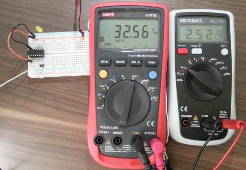
The following example should illustrate the basic concept. It uses no prescaler to get the maximum frequency. The waveform generation mode is set to 8-bit Fast-PWM, which means that the top value of the counter is 255, and the compare output mode is set to non-inverting mode on Arduino pin 6. The register OCR1A is set to 127, which results in a duty cycle of 50%.
void setup() {
    pinMode(6, OUTPUT);

	/*
	 * WGM10, WGM12: Fast PWM, 8-bit TOP=255
	 * CS10: No prescaler
	 * COM1A1: Pin 6 to LOW on match with OCR1A and to HIGH on TOP
	 */
	TCCR1A = _BV(COM1A1) | _BV(WGM10);
	TCCR1B = _BV(CS10) | _BV(WGM12);
	/*
	 * 50% duty cycle
	 * 32 kHz with 8MHz CPU clock
	 */
	OCR1A = 127;
}

void loop() {
}
Advanced Fast-PWM Configuration

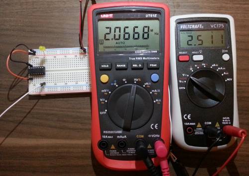
One simple way to get higher frequencies, is to lower the top limit of the counter. This reduces the number of steps we have available for setting the duty cycle, but it increases the maximum possible frequency.
By choosing a wave generation mode with a variable top limit, we can generate crazy high frequencies.
void setup() {
    pinMode(6, OUTPUT);

	/*
	 * WGM11, WGM12, WGM13: Fast PWM TOP=ICR1
	 * CS10: No prescaler
	 * COM1A1: Pin 6 to LOW on match with OCR1A and to HIGH on TOP
	 */
	TCCR1A = _BV(COM1A1) | _BV(WGM11);
	TCCR1B = _BV(CS10) | _BV(WGM12) | _BV(WGM13);

	// Set TOP to 3, so 25%, 50% 75% 100% duty cycles are possible
	ICR1 = 3;
	/*
	 * 50% duty cycle
	 * 2 MHz with 8MHz CPU clock
	 */
	OCR1A = 1;
}

void loop() {
}
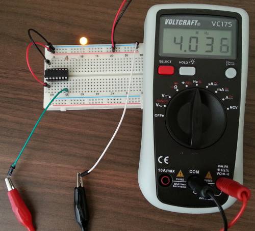
If you only need a square wave with a 50% duty cycle and nothing else, then you can also get the maximum frequency of half the CPU clock speed. In toggle mode the timer counts up to the value in OCR1A and then toggles the output pin. By setting OCR1A to 0 the output pin is switched from LOW to HIGH on every CPU clock cycle, which results in a frequency of \(\frac{CPU\:clock\:frequency}{2}=\frac{8\:MHz}{2}=4\:MHz\).
void setup() {
    pinMode(6, OUTPUT);

	/*
	 * WGM10, WGM11, WGM12, WGM13: Fast PWM TOP=OCR1A
	 * CS10: No prescaler
	 * COM1A0: Toggle Pin 6 on TOP
	 */
	TCCR1A = _BV(COM1A0) | _BV(WGM11) | _BV(WGM10);
	TCCR1B = _BV(CS10) | _BV(WGM12) | _BV(WGM13);

	/*
	 * 50% duty cycle
	 * 4 MHz with 8MHz CPU clock
	 */
	OCR1A = 0;
}

void loop() {
}
Calculating the Frequency
The formula for calculating the resulting frequency on the output pin is straight forward:
$$f = CPU\:clock\:frequency \div Prescaler \div (TOP\:limit + 1)$$Conclusion
The Arduino API is definitely very limiting when it comes to PWM settings and it is quite astonishing what the hardware is capable of. Unfortunately I do not own an oscilloscope, so I cannot check how clean the generated waveforms are. I suspect, that the high frequency waveforms like 4 Mhz have distortions in them and are not perfect square waves.
References
- Pulse-width modulation - https://en.wikipedia.org/wiki/Pulse-width_modulation
- Attiny84 Datasheet - http://www.atmel.com/Images/doc8006.pdf